Step 1 | ||
 | This is the Sketchup file continued from the last tutorial. | |
Step 2 | ||
 | Start off by deleting Susan. | |
Step 3 | ||
 | Ensure that the "SKP - External Walls" layer is selected, and then using the line tool draw around the internal edge of the external walls until a surface is recognised. You should only need to draw five straight lines and one arc. If you have trouble seeing what you are drawing then have a look at the Screenshot from Step 5, which shows what you are drawing now with the AutoCAD layers turned off. | |
Step 4 | ||
 | Now draw around the external edge of the external walls. | |
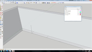
Step 5 | ||
 | Turning off all of the AutoCAD layers should leave you with something that looks like this. | |
Step 6 | ||
 | Delete the face in the centre. | |
Step 7 | ||
 | Double click on the remaining face to select it and it's bounding edges and then make it into a component. Call the component "External Walls" and ensure the "Replace selection with component" is TICKED. | |
Step 8 | ||
 | Go into the component editor and push pull the face upwards by "2400". You can now exit the component editor. | |
Step 9 | ||
 | Turn on the "ACAD - External Walls" Layer, as well as the "X-Ray" style. This should allow you to see the lines for where the windows openings are as shown. | |
Step 10 | ||
 | Using the line tool you can measure the window opening. To do this click on the first point, when you hover over the endpoint the measurement is shown in the bottom right hand corner. In this case the measurement is 1800, so the window needs to be 1800 wide. | |
Step 11 | ||
 | Working outside of the External Walls component, point the line vertically upwards and make it 900 long as shown. | |
Step 12 | ||
 | Now go into the External Walls component. Remember that the indicator that you are in a component is the black dotted line around the outside, but you can also see that the 900mm line you have just drawn has gone quite faint. Everything outside of the component which you are within will look fainter when you are in the component editor mode. | |
Step 13 | ||
 | Use the rectangle tool, and click on the top end point of the line. This will be the starting point of our window opening. Point the rectangle up and to the right, then type in "1800 COMMA 1200". This will create a rectangle that is 1800mm across and 1200 up. | |
Step 14 | ||
 | Using the push pull tool click on the surface formed where the window will be. You can now snap it to the other side of the wall just by hovering the cursor over the top edge of the otherside. You should get a red snap point. | |
Step 15 | ||
 | Now exit the component editor by double clicking outside of the current component. | |
Step 16 | ||
 | Delete the 900mm working line and turn off "X-ray" style. | |
Step 17 | ||
 | Now try repeating this process for the other rectilinear window and the door. The outcome shown here. | |
Step 18 | ||
 | We now need to create the window opening for the dormer window. Draw a horizontal line across the diameter of the arc as shown, and then from the midpoint of that line, draw a line vertically at 900mm. Point the line tool through the centre of the dormer wall now and it should snap to the red axis. Enter a value of 3000, and then from the endpoint of that line, point a new line vertically upwards by 900. | |
Step 19 | ||
 | Use the rectangle tool and click on the end of this most recent line. | |
Step 20 | ||
 | If you snap the opposite corner of the rectangle to the end of the 3000mm line inside the wall you will then create a surface as shown here. | |
Step 21 | ||
 | Double click on the surface to select the surface and it's enclosing edges, then right click and make it into a group. We are only going to need to use this shape once so we do not need it saved in the file as a component. | |
Step 22 | ||
 | With the new group selected, choose the "Rotate" tool (Shortcut - Q) and set the centre of rotation on the ground plane at the midpoint of the diameter of the arc. The protractor should be before you click. Extend your cursor out beyond the wall and click somewhere that is not part of your model. This will establish a reference line for your rotation. | |
Step 23 | ||
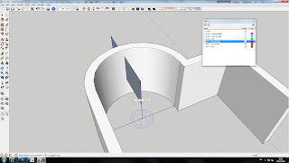 | As you move the cursor now you will see the component rotates around the centre of rotation. Point it in the direction shown, enter a value of 45, (for 45 degrees) and press enter. | |
Step 24 | ||
 | Now enter the group editor by double clicking on it, and select the face of the rectangle. | |
Step 25 | ||
 | Select the rotate tool again, and click at the centre point of the arc diameter, ensuring that the protractor is blue before you click. You then need to specify the reference line, I would tend to recommend making it along the red axis just to make it clearer what it is you are doing. Be aware that the red axis will have changed here as it will be the red axis of the "group" rather than of the entire model space. This is not a problem, so we still want to use this as a reference line. | |
Step 26 | ||
 | Once you have specified the reference line you can see the face moves around as it did before. If you press the "ctrl" key then you will see that it leaves the original and just creates a copy. Do this and to create a copy and set it at an angle 90 degrees around from the original. | |
Step 27 | ||
 | You should have something that looks like this. Note that both faces are within the same group. | |
Step 28 | ||
 | Using the line tool, and working within the group editor draw two lines as shown to create a triangular prism. | |
Step 29 | ||
 | If the faces created by Sketchup are white you do not need to follow the next step - although you should still be aware of the process. If you have blue faces it is important to do this. | |
Step 30 | ||
 | If you right click on a blue face and select "Reverse Face", then it flips the face around to show the other side, the white side. In Sketchup the white face is the front face and the blue face is the back. It is good practice in Sketchup to always have the front face facing outwards as this will save having any problems with "Sketchup Solids" or external renderers. | |
Step 31 | ||
 | If you have at least one face which is correct, i.e. white, you can right click on that face and select "Orient Faces" in which case all faces should now orientate white outwards. Note on more complex geometries this does not always work! Note that if you do not have Sketchup Pro, or for some reason you have not created Sketchup Volumes then the Solid Tools will not work, and you will have to follow the alternative method as shown in the following tutorial. | |
Step 32 | ||
 | You should now have something that looks like this. | |
Step 33 | ||
 | Using the "Subtract" tool from the "Solid Tools" tool panel, you now need to subtract the triangular prism from the external walls. | |
Step 34 | ||
 | That should leave you with something looking like this. | |
Step 35 | ||
 | Just to finish off the process delete the working lines. | |
Step 36 | ||
 | Now the windows are finished. | |
Sunday 18 March 2012
04. Creating the External Walls
Subscribe to:
Post Comments (Atom)
No comments:
Post a Comment