Step 1 | ||
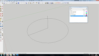
 | Make sure you have the "SKP - Roofs" layer set as the current layer. Then you need to draw a line from the midpoint at the top of the external wall shown here, vertically upwards by 1800mm. | |
Step 2 | ||
 | We a going to draw the top triangle of a gable end, so now click to draw a line to the left hand corner as shown. | |
Step 3 | ||
 | Now draw directly to the right hand corner, this should create a half triangle surface. | |
Step 4 | ||
 | Now complete the triangle by clicking again at the top. You can select and delete the centre line. | |
Step 5 | ||
 | Select the face and enclosing edges and make into a component - "Roof 1", replace selection with component. | |
Step 6 | ||
 | Enter the component editor then push pull the surface. Notice that half-way through an action you can re-orientate your view as necessary if you use the mouse wheel to do so, i.e. for orbiting etc... | |
Step 7 | ||
 | Re-align your view to allow you to see the snap point on this side of the building. You have now completed the first part of the roof. Exit the component. | |
Step 8 | ||
 | Draw a line at the top of the External walls across the external diameter of the dormer arc. | |
Step 9 | ||
 | From the centre point draw a line upwards until you get a blue line which snaps to the pitched edge of the existing roof 1 component. | |
Step 10 | ||
 | From the arc centre point we now need to draw a small working platform which our next tool will align to. Draw a small line along the red axis. | |
Step 11 | ||
 | From the end of this line complete a triangular surface by completing it to somewhere along the arc diameter. | |
Step 12 | ||
 | You can now use the circle tool. When you select the central point you should see blue triangle, this means that it is on the Red/Green plane which is what we want, so click to set the centre point. | |
Step 13 | ||
 | Now set the radius of the circle by clicking on the external edge of the dormer wall. Notice that as the circle is gradated (and is actually a 24 sided shape) it will either align with the external walls below, or it will not. For the next steps to work it must align with the walls below. | |
Step 14 | ||
 | Notice that the circle is a mixture of blue and white. This is because the face of the circle is overlapping a face of the external walls, but for now we shall not worry about this. | |
Step 15 | ||
 | Right click on the roof 1 component and select "hide". Do the same for the External Walls component. | |
Step 16 | ||
 | We now want to delete the surface of the circle and the working triangle which we used previously to achieve something that resembles the picture in the next step. | |
Step 17 | ||
 | As so. | |
Step 18 | ||
 | Complete a triangle by drawing a line between the two points shown. | |
Step 19 | ||
 | The next tool takes a little bit of getting used to and may take a few attempts. Select the "Follow Me" tool, and click on the face of the triangle. You now need to very gradually move the cursor around the perimeter of the circle. | |
Step 20 | ||
 | As you get to the end it should look something like this. | |
Step 21 | ||
 | You can end the follow me by clicking but you want to finish the cone so make sure it is at the point where the triangle meets the circle. | |
Step 22 | ||
 | Depending on which direction you led the triangle around the circle will depend whether the cone is white or blue. You want it to be white as this will suggest it has created a "Google Solid" and that the cone has a base.>br /> If it is blue you can flip faces as earlier and just quickly draw a base on the cone. Select the entirity of the cone and make it into a component "Roof 2". | |
Step 23 | ||
 | From the top menu select "Edit -> Unhide -> All". | |
Step 24 | ||
 | To combine the two roofs I have used the "Outer Shell" tool to combine the two roofs. In the trial version of Sketchup you would need to do achieve the same affect by intersecting the two objects together and deleting the overlaps as shown in the previous tutorial. | |
Step 25 | ||
 | When working within a group or component you can right click on an individual line or face and set it to hide. Doing this will mean that the surface or line will not automatically unhide when you perform the "Unhide All" option unless you are in the component editor mode of the corresponding component. This is quite handy as we can hide lines like this one here which we don't want to be visible, but equally we do not want it to automatically re-appear later if we perform another "unhide all". | |
Step 26 | ||
 | The model should now look something like this. | |
Sunday 18 March 2012
06. Roofs
Subscribe to:
Post Comments (Atom)
No comments:
Post a Comment